What the copilot does
The method is described in Communications Engineering, where it was accepted and published on 10 November 2026. MIT News publicised the work on 13 November. Dat Quoc Ha led the study, Josephine Carstensen is the senior author, and Ferdous Alam, Markus Buehler and Faez Ahmed are co-authors.
Topology optimization is the process of letting an algorithm decide where material should sit inside a given volume so the part carries its loads with as little mass as possible. It is standard in aerospace, automotive and civil engineering, and it has always had the same weak point. The solver optimises for a mathematical objective, not for a workshop. Results get exported, cleaned up by a human, and often lose much of the efficiency that made them interesting in the first place.
The MIT system changes the order of those steps. A U-Net, trained on synthetic preference data, watches the geometry as it evolves and highlights regions where a human decision would actually change the outcome. The engineer can ask for a region to be thickened or thinned. The solver takes that input and keeps going. There is no separate rebuild stage afterwards.
The three numbers in the paper
39% is the headline figure: an improvement in linear buckling load in the study's sample tests. Buckling is what happens when a slender member folds under compression long before the material itself fails, and it is the constraint that governs a lot of steel and aluminium design. A structure that resists it better can often be lighter.
15 seconds is the added computational cost of the human loop per design run, measured against standard automated topology optimization. That is the number that decides whether a tool like this survives contact with a real project. Interactive systems that take minutes per interaction get abandoned; ones that respond in seconds get used.
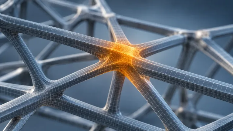
Eight beams is the kind of artefact the system targets. Where eight or more members converge on a single node, the geometry may be optimal on paper and unmanufacturable in practice. The copilot flags those zones so the engineer can intervene before the solver commits to them.
What 15 seconds per run actually costs
The arithmetic is simple enough to do in your head. An engineer exploring a design space might run a hundred optimization passes in a working day. At 15 seconds each, the feedback loop adds 25 minutes to that day. If the session is shorter, say twenty passes, the overhead is five minutes.
Put against the alternative, those minutes look cheap. Manual cleanup of a topology result in CAD is measured in hours, and the cleanup is where the weight savings tend to evaporate. The trade the paper describes is a small, predictable amount of machine time against a large, unpredictable amount of human rework.
Compute is not the bottleneck either. A U-Net operating on density grids is a small model by current standards, far below the memory footprint of the language models we benchmark on the AI Arena rig. A 16 GB consumer GPU is comfortable territory for this class of network. A design office can plausibly keep the whole loop on a workstation rather than shipping geometry to a cloud API, which matters for anyone protecting client data.
What the paper does not show
The 39% figure comes from sample tests in a research paper, not from a commissioned building or a production bracket. Nothing in the announcement suggests the method has been validated against a full structural code check, a fatigue assessment or a real fabrication trial. Treat it as a signal about direction, not a specification.
The U-Net was trained on synthetic preference data, which means the model learned a simulated idea of what engineers want. Whether that transfers to the preferences of an actual design team at an actual consultancy is an open question. Preference data is also where bias enters quietly: a model trained on one firm's habits will reproduce them.
MIT News describes a research method. No commercial plugin, pricing or release date is announced, so there is nothing to buy or download today.
The European side: codes, liability and timing
For European structural engineers, the interesting question is not whether the geometry is better. It is who signs it off. Buckling verification in steel design runs through EN 1993-1-1, where the recommended partial factor for member stability, γM1, is 1.0, though National Annexes can set their own values. With γM1 = 1.0 there is no reduction factor on the buckling resistance itself — the safety reserve sits in the load factors — so a 39% gain in resistance from geometry is far larger than anything the stability partial factor contributes. It is not a like-for-like comparison, and no authority would accept it as one.
On regulation, the deadlines moved. The Digital Omnibus on AI, Regulation (EU) 2026/1744, postponed the Annex III high-risk obligations to December 2027 for standalone systems and August 2028 for embedded products. Whether a design assistant lands in that category depends on how it is deployed, particularly where a system acts as a safety component in critical infrastructure. A tool that proposes geometry and leaves the engineering judgement with a named person sits in a different position from one that issues the design.
That is why the human-in-the-loop design of this prototype matters beyond usability. A traceable record of which regions an engineer changed, and why, is the kind of documentation that makes an algorithmic design defensible in a review meeting.
Does the 39% buckling improvement apply to real structures?
No. The figure comes from the sample tests reported in the Communications Engineering paper. It has not been verified against a full code check such as EN 1993-1-1, a fatigue assessment or a fabrication trial.
Can I use this in my CAD workflow today?
Not from this announcement. MIT News describes a research method with no stated commercial integration, licence or release date.
What hardware would a tool like this need?
The machine-learning component is a U-Net working on density grids, a much smaller model than a language model. That puts it within reach of a workstation GPU rather than a datacentre, which also keeps proprietary geometry in-house.